Aerospace Engineering Β· Virginia Tech

Hi, I'm Maddie

I'm an aerospace engineer from Virginia Tech who loves turning ideas into real, working projects β€” from 3D-printed robot arms to a NASA-finalist Mars mission concept. Off the clock, I'm drawing, painting, or outside hiking, riding boards, and chasing good light with my camera.

1 of 14
teams selected nationwide for
NASA's 2025 RASC-AL Competition
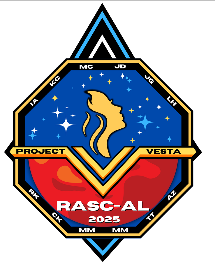
The RASC-AL seal β€” Revolutionary Aerospace Systems Concepts Academic Linkage The Project VESTA mission patch β€” a diamond badge carrying the team's initials, a torch-bearing figure over a starfield, and Mars below

A national field, judged by NASA.

RASC-AL is NASA's Revolutionary Aerospace Systems Concepts β€” Academic Linkage competition, open to undergraduate and graduate teams at accredited universities across the country. Fourteen made the final cut in 2025 and presented to a panel of NASA and aerospace industry judges in Cocoa Beach.

Virginia Tech MITTexas A&MMaryland Arizona StateIllinoisTulane South Dakota StatePuerto Rico–MayagΓΌez
Theme
Human-Mars Precursor Campaign
Forum
June 2–4, 2025 Β· Cocoa Beach, FL
Award
$6,500 finalist stipend
Read NASA's finalist announcement β†’

Project VESTA.

Mars ISRU
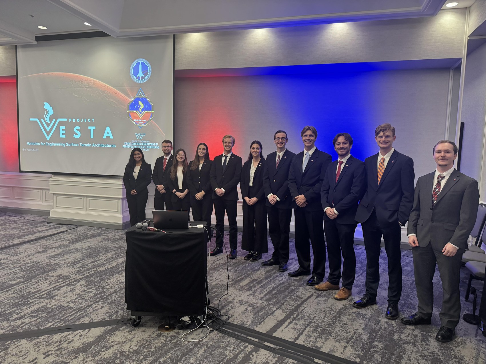
The 13-person VESTA team on stage at the RASC-AL Competition Forum

Systems engineering at mission scale

Systems integrationEnvironmental managementRisk analysisMission architecture

A Martian precursor mission that lands a semi-autonomous network of collection, processing, and construction systems in Jezero Crater β€” then proves the architecture by building a 30-meter landing pad entirely from resources already on the ground. I led environmental management and systems integration: how the systems interact and protect one another, and where everything sits on the surface.

13-person team30 m landing pad7,084 interlocking pavers7 routes traded$23.3 B

V6 Assembly.

SolidWorks
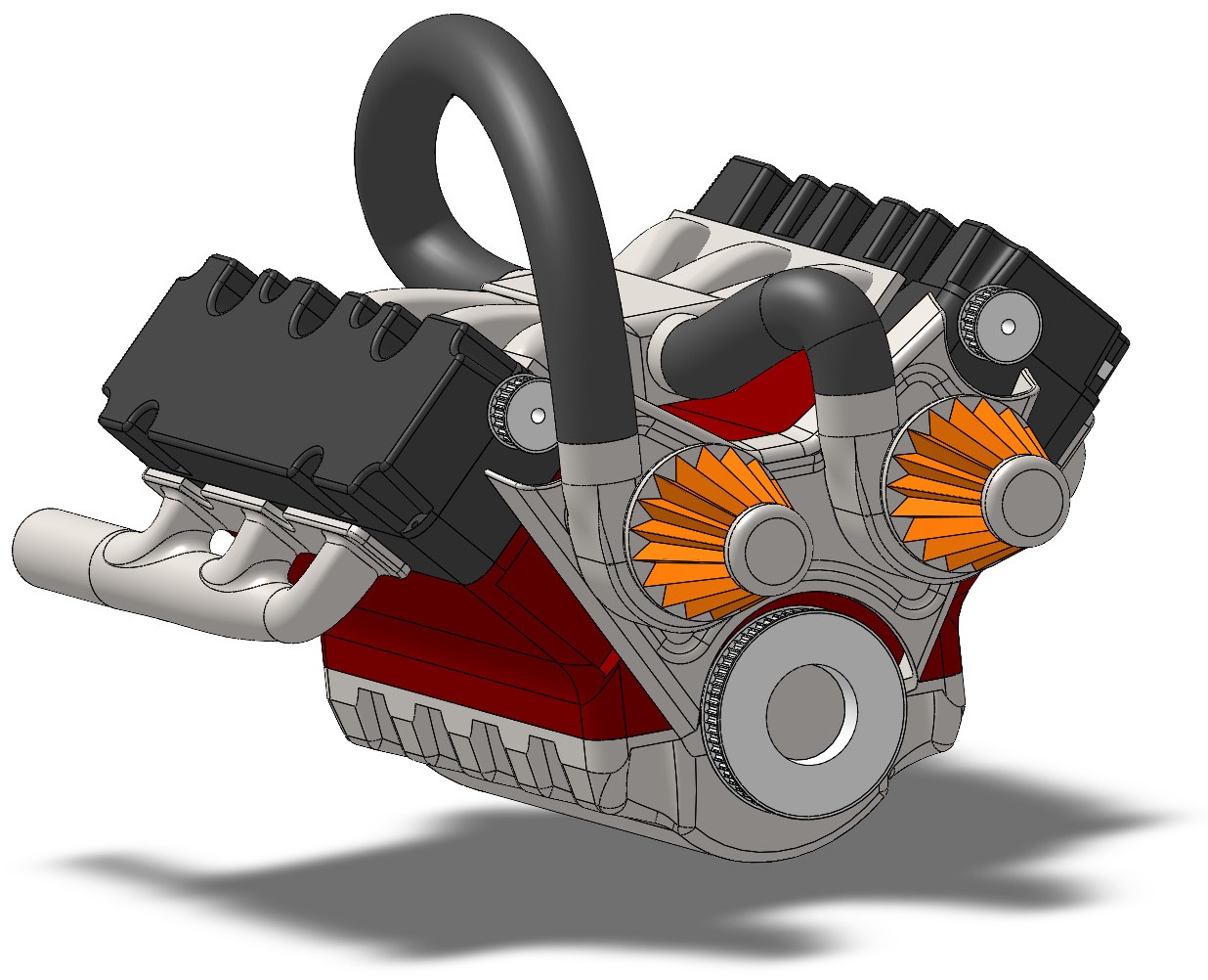
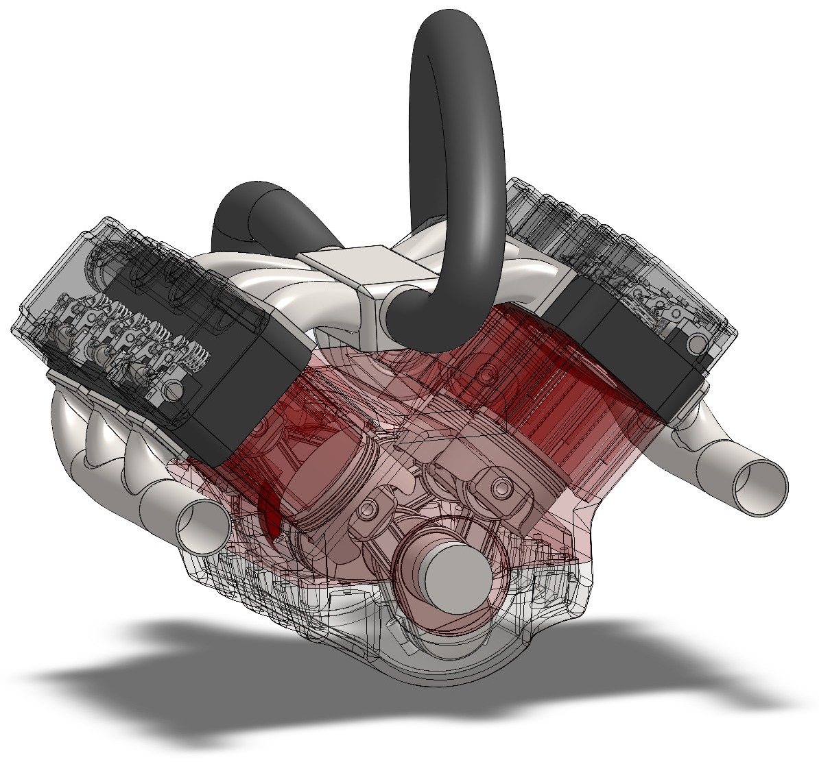
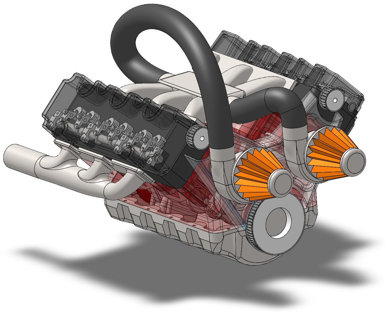
Transparent SolidWorks render showing the V6 valvetrain and rocker arms

Assembly modeling, from part to BOM

SolidWorksPart modelingEngineering documentation

Built the way a real engine goes together β€” block first, then the crankshaft and its bushings, six pistons with pins, rods, and caps, the heads, twin cams on eight retainers, twelve valves under twelve rocker assemblies, then manifolds, covers, and twin turbos.

Independent project30 unique parts12 valves24 rocker wheels

Robotic Arm.

Robotics
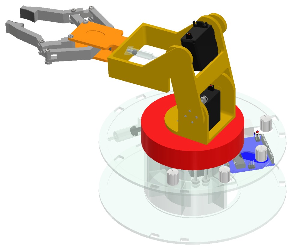
Color CAD render of the four-axis robotic arm with its claw extended

Project management, from concept to hardware

Team leadershipDesign selectionBudget controlMechatronicsRapid prototyping

Four concepts went into a weighted design matrix. Mine scored 82.55 and got built, largely on weight: it was the only design that kept the servos off the top arm and out of the gripper. I ran the project from there β€” schedule, budget, and the split of fabrication work.

Team of 34 degrees of freedom4Γ— MG995Hydraulic claw$94.25 of $100

Solar Tracker.

Solar energy
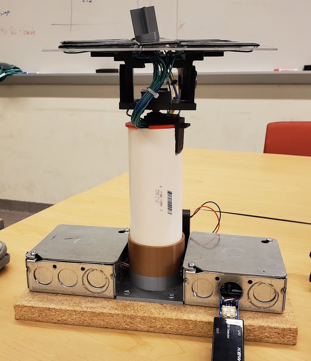
The completed dual-axis solar tracker prototype

Scope management, from stretch goal to working build

Team leadershipRequirementsElectromechanical systems

Four photoresistors sit in a voltage-divider bridge at the corners of the array. The control loop reads all four, compares quadrants, and steps each servo toward whichever corner is brightest β€” holding ten panels normal to the sun on two axes.

Project managerTeam of 42 axes4 photoresistors10 panels12 Γ— 12 Γ— 12 in envelope

For fun

What I make and do when nobody's grading it. Open a card to see the rest.

Art & Photography

18 pieces Β· graphite, ink, colored pencil, acrylic, oil, and photography

White koi drawn on dark brown paper
A red tulip photographed from directly above, petals open around the dark center
Graphite portrait drawing of a face looking straight ahead
Black and white photograph of a horse grazing under bare trees
Painting of a green and orange Mandalorian-style helmet against a blue background
Black and white close-up of an orchid against a dark background
Ink and wash drawing of a crouching figure lifting a fish overhead in the rain
Pink redbud blossoms growing directly from tangled branches
Painting on tall canvas of a breaking wave above dark cliffs
Black and white photograph of a wooden fence line receding along a planted border
Colored pencil sketchbook drawing of an iced coffee, pencils resting on the open page
Silver-veined lamium leaves filling the frame
Painting of a fish over a copper and blue washed background
Black and white photograph of a horse grazing beyond a fence rail
Yellow tulips and purple alyssum planted in overlapping drifts
Black and white study of dense grass filling the frame
Flowering trees in pink and copper against a blue spring sky
Yellow euphorbia bracts opening above red-tinged leaves

Outdoors

20 photos Β· ridgelines, snow, water, and skateparks

Three hikers standing on a rocky summit above a ridgeline
A jagged rock outcrop rising above a valley under a blue sky
Madeline sitting strapped into a snowboard at the top of a sunlit slope
Boots resting on rock at a summit, layered blue ridges and low cloud beyond
The bow of a kayak on flat water lined with trees
Madeline in a beanie and sunglasses on a summit with mountains behind
A tall rock spire among bare trees against a blue sky
Two snowboarders in goggles and face coverings riding a chairlift through snowy pines
Two hikers smiling beside a rocky creek below a waterfall
Bare rock foreground opening onto a hazy valley at sunrise
A lit tent at night with someone sitting inside
Madeline riding a skateboard off a ledge at a skatepark
Rock outcrop and rolling blue ridges under a clear sky
Two people in wetsuits on the beach after surfing
A waterfall falling into a shallow river with someone wading below
Packed lunch boxes and a flask spread out on rock at a viewpoint
Hiking boots on a summit ledge above a wooded valley
Madeline in snowboard gear beside a pickup truck in a snowy parking lot
A resting spot on bare winter rock with an open ridge beyond
Two friends bundled in hats and coats smiling at the camera

Let's build something.

I'm looking for roles in test and integration, aerospace, mechanical, and systems engineering. Happy to walk through any of this in detail.

crumrmadeline@gmail.com

Project VESTA

Vehicles for Engineering Surface Terrain Architectures β€” a Martian precursor mission that builds its own landing pad.

Role
Environmental management & systems integration
Team
13 engineers Β· advised by Dr. Kevin Shinpaugh
Discipline
Space systems / ISRU
Outcome
NASA RASC-AL finalist

The mission

NASA's brief asked for advanced science missions and technology demonstrators for a human-Mars precursor campaign. Ours lands a semi-autonomous network of collection, processing, and construction systems in Jezero Crater and demonstrates the whole architecture by building something a later crewed mission actually needs: a 30-meter landing pad.

The site picked itself. Jezero has eight scientific regions of interest across 1,600 kmΒ², five distinct resource varieties, confirmed subsurface ice, and science heritage from Perseverance. Its uniform crater structure also allows precise beacon placement and safer landings.

The heart of the work was the trade on how to turn regolith into something load-bearing. We carried seven processing routes through compressive strength and thermal limit β€” sulfur concrete reaches 54 MPa but softens by 390 K, so it's only good for temporary structures; magnesium silica holds to 1300 K at 40 MPa; calcium aluminate tops the set at 85 MPa and 1300 K, which is what put it under the foundations.

The pad itself is an octagon roughly 30 meters across, built on a NASA–SIDUS Space interlocking paver design: 3,542 polygon pavers and 3,542 spacer pavers that fit together to constrain all six degrees of freedom and stop engine exhaust from escaping through the seams. The same interlocking approach extends upward into berms and habitat walls using octagonal interlocking bricks.

My role

I led environmental management and systems integration for the mission: working out how VESTA's systems should interact with and protect one another, and where everything should be laid out on the surface.

That meant applying hazard analysis β€” dust, radiation, thermal extremes β€” to habitat-deployment logistics, surface infrastructure, construction operations, and the overall mission architecture. I developed an Analytic Hierarchy Process framework to prioritize those crew and system risks, and pulled the subteams' work together into the technical documentation, engineering figures, and final NASA RASC-AL presentation.
Mission parameters
Landing pad
30 m
Polygon pavers
3,542
Spacer pavers
3,542
Processing routes
7 traded
Selected method
Calcium aluminate
Compressive strength
85 MPa
Thermal limit
1300 K
Extended dry mass
165 mt
ISRU dry mass
60 mt
Total cost
$23.3 B
Operational cost
$0.7 B
Shortfalls retired
5

From the forum

The 13-person VESTA team on stage at the RASC-AL Competition Forum
The team. Presenting Project VESTA to NASA and industry judges, Cocoa Beach, June 2025.
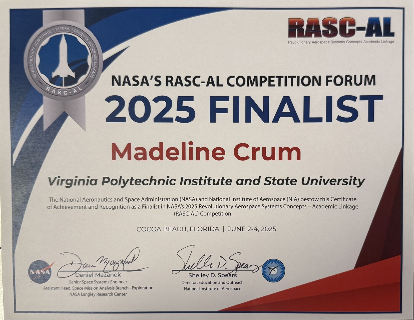
NASA RASC-AL 2025 Finalist certificate awarded to Madeline Crum
Finalist recognition from NASA and the National Institute of Aerospace.

The digital poster

The full technical poster submitted to NASA β€” mission architecture, the processing-method trade, rover and lander systems, mass and cost breakdowns, and the campaign timeline out to 2050.

V6 Engine Assembly

A complete V6 modeled part by part in SolidWorks, then mated into one assembly with a bill of materials driven off the tree.

Role
Sole designer
Team
Independent
Discipline
CAD / mechanical
Outcome
30-part assembly with BOM

Built like the real thing

The assembly follows the order an engine is actually built in. The block comes first, then the crankshaft riding two bushings. Six pistons get pins, rods, and rod caps. The cylinder heads drop on, then twin camshafts held by eight retainers, and under them twelve valves with twelve rocker assemblies β€” each rocker its own body, pin and pair of wheels, which is where most of the part count lives.

Manifolds, valve covers, a front cover, and belt wheels close it out, and two turbos with filters sit on the intake side. Thirty unique parts resolve to well over a hundred instanced components once quantities are applied.

The point of the exercise was the assembly discipline as much as the modeling: mates that hold when parts change, and a bill of materials generated from the assembly tree rather than maintained as a separate list that drifts out of date.

Bill of materials
Unique parts
30
Rocker arm wheels
24
Rocker arm pins
24
Valves
12
Rocker springs
12
Pistons
6
Piston rods
6
Camshaft retainers
8
Cylinder heads
2
Camshafts
2
Turbos
2

The model

Shaded SolidWorks render of the completed V6 assembly
Completed assembly, shaded. Twin turbos and filters on the intake side, exhaust manifolds below.
Transparent render revealing the valvetrain inside the cylinder heads
Transparent view. Twelve valves and their rocker assemblies visible under the covers.
Second transparent view of the V6 from a different angle
Second transparent view, through the heads and intake manifold.

Four-Axis Robotic Arm

A 3D-printed arm with a syringe-driven hydraulic claw, built to a $100 budget from my own concept.

Role
Project manager
Team
3 engineers
Discipline
Robotics / fabrication
Outcome
Built for $94.25 of $100

Winning the design matrix

Each of us brought a concept, and we scored all four against weighted criteria we'd agreed up front β€” functionality 35%, originality 30%, weight 15%, complexity 15%, and cost 5%. Mine came out at 82.55 of 100, ahead of 79, 73.5, and 70.

It won on weight, where it scored a perfect 10: it was the only concept that kept the servos off the top arm and out of the gripper, so the mass stayed low and the base stayed planted. The tradeoff was cost β€” a hydraulic claw is more expensive than a servo-driven one β€” and the open risk that the actuation might not be precise enough. It proved precise enough.

Running the build

As project manager I owned the schedule, the budget, and who did what. We ran procurement from March 5th, part fabrication from the 10th, and staged the frame, electrical system, and code in parallel so system integration could start April 7th, leaving two weeks for testing and troubleshooting.

Preliminary CAD was detailed enough that fabrication needed only four revisions: a thicker bottom plate, fillets at the load paths, a slit in the side for the middle-arm knob, and the rotation servo moved down onto the middle arm with a pocket cut to clear it. Coming out of it, the team's own read was that being detail-oriented early is what let us start fabricating ahead of schedule.

Build specification
Degrees of freedom
4
Servos
4Γ— MG995
Stall torque
12 kgΒ·cm @ 6 V
Operating voltage
3.0–7.2 V
Speed
0.13 s / 60Β°
Controller
Arduino Uno
Input
4 potentiometers
Claw actuation
Hydraulic
Print time
< 27 h
Design matrix score
82.55 / 100
Final cost
$94.25

Concept to hardware

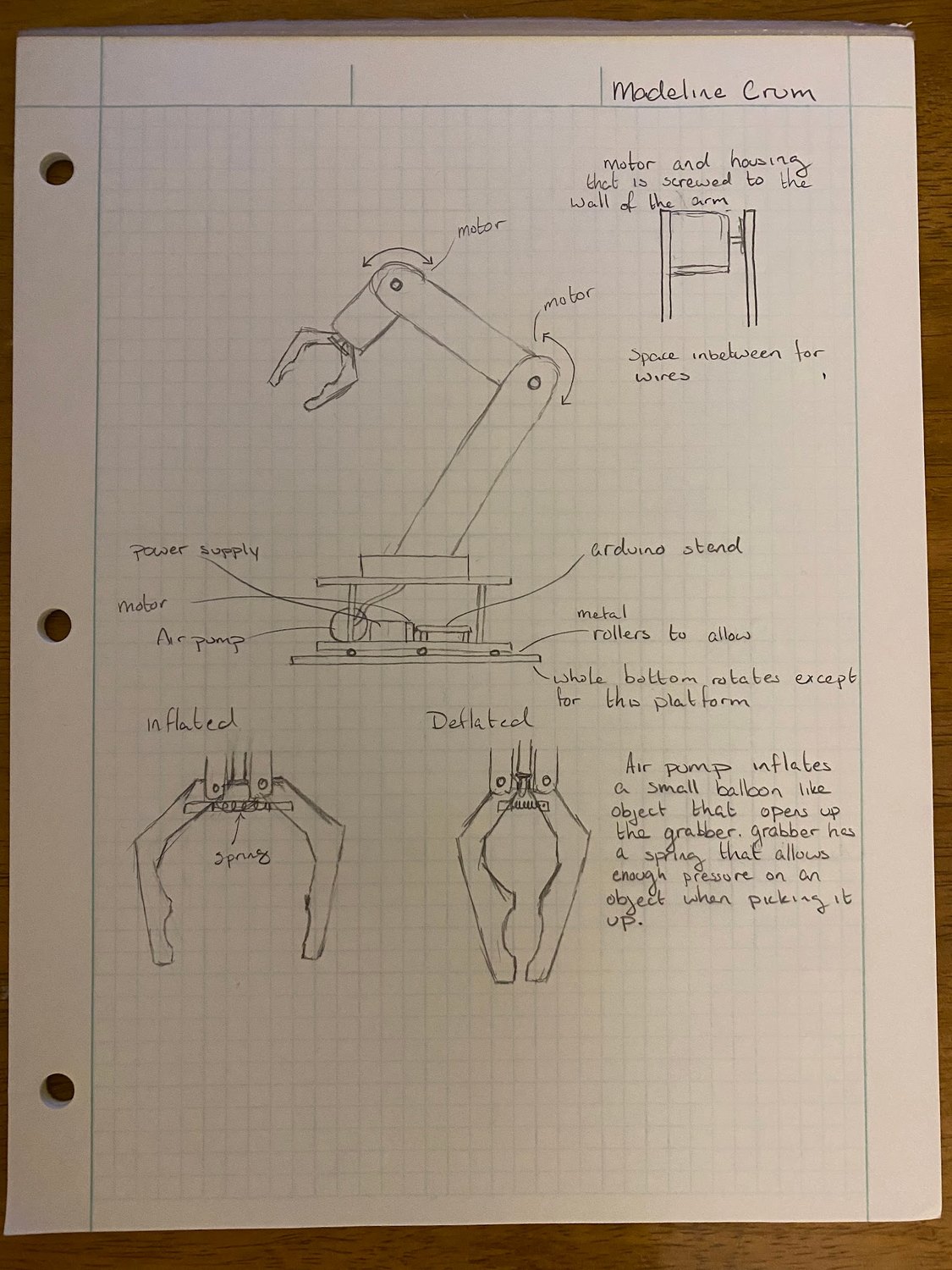
Madeline's hand-drawn concept sketch of the robotic arm with annotated gripper mechanism
The winning concept. My preliminary sketch β€” motor housings screwed to the arm walls, wiring channels between, and an inflate-to-open gripper with a spring return.
Color CAD render of the full robotic arm assembly with the claw extended, showing the syringe, servos, potentiometers, and Arduino
Full assembly in CAD, claw extended β€” the syringe that drives the hydraulic claw, the servos mounted on the arm, and the potentiometers and Arduino housed in the base.
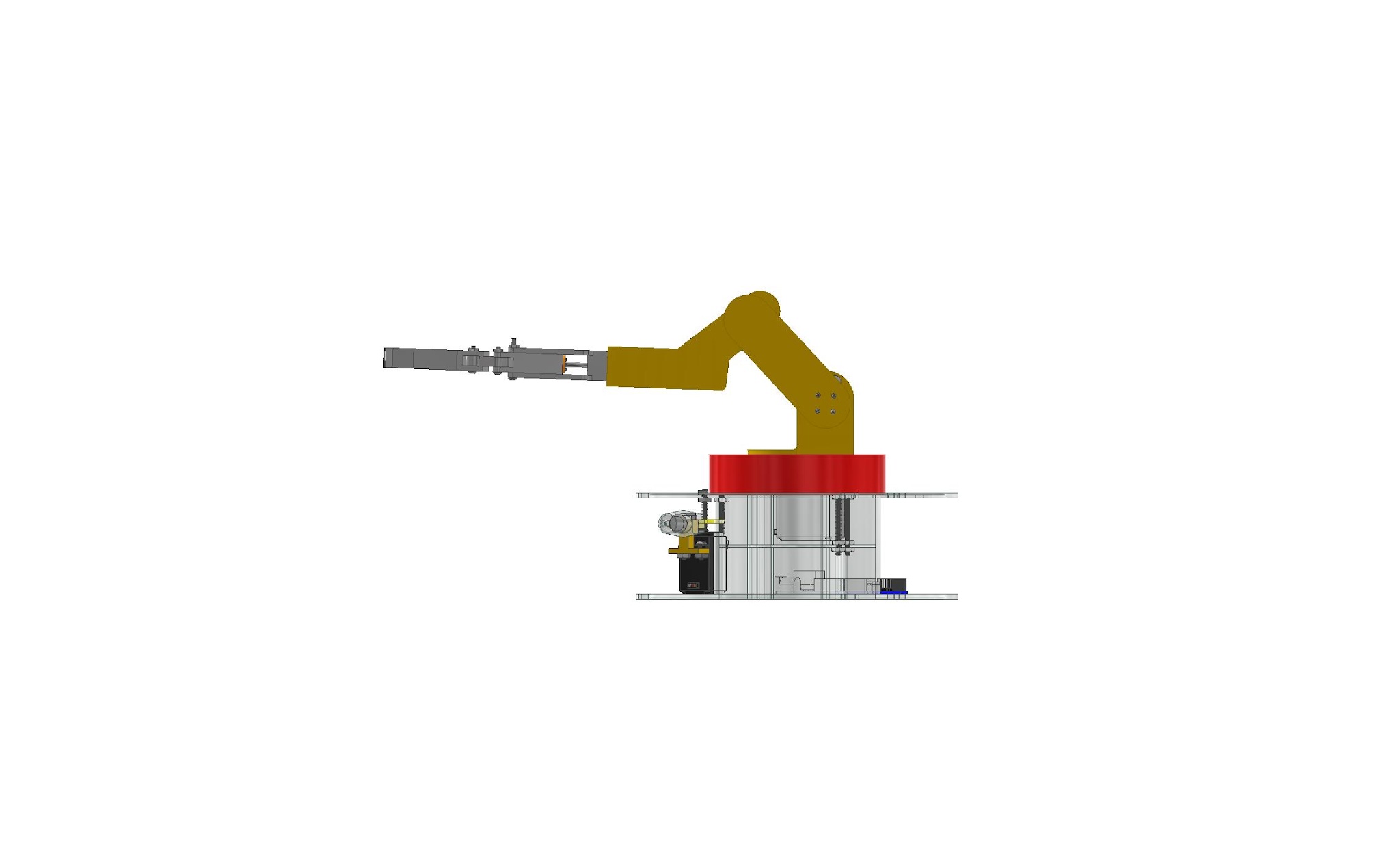
CAD side elevation of the arm fully extended
Side elevation, fully extended.
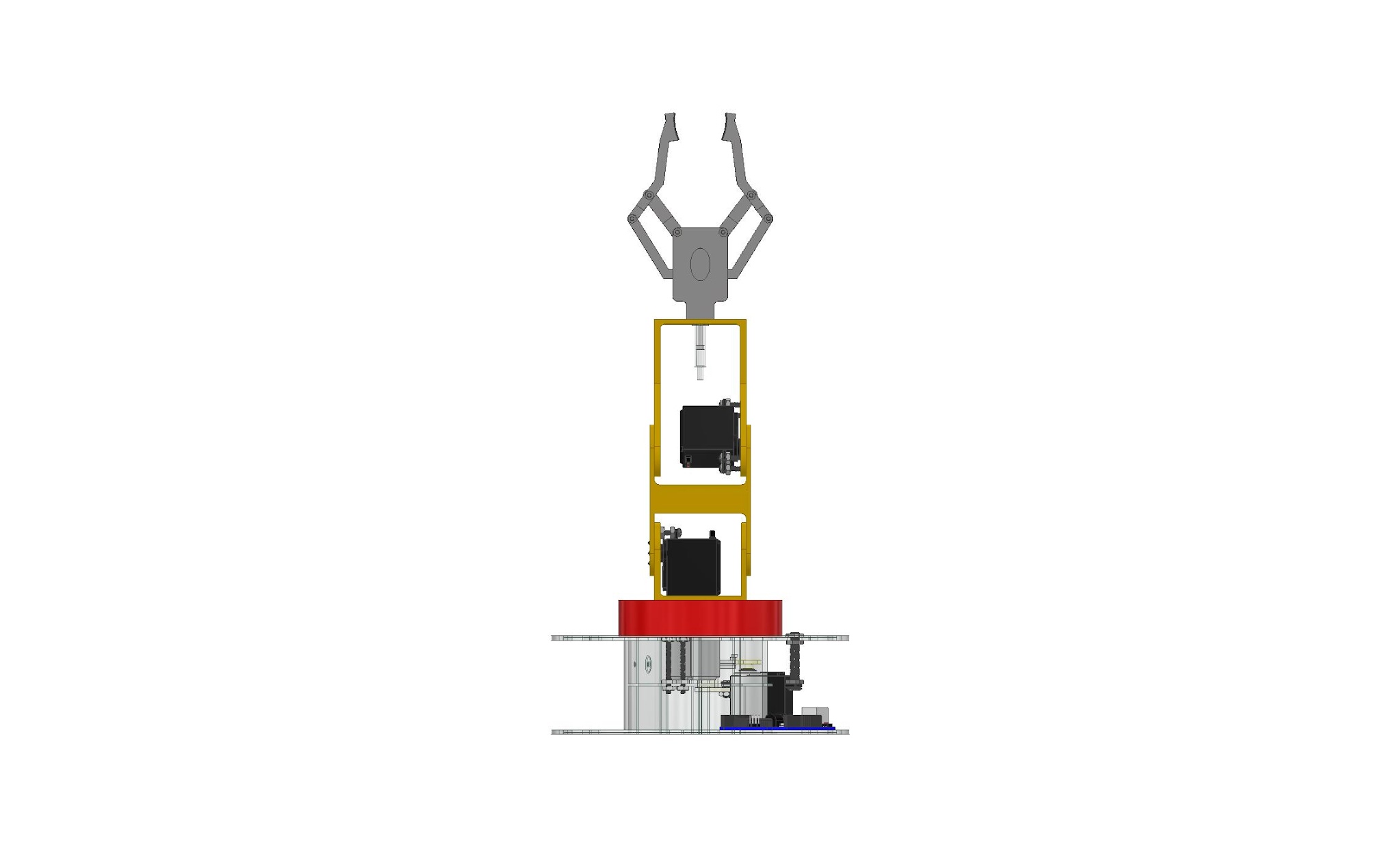
CAD front elevation of the arm with the claw raised
Front elevation. Servos sit inboard on the middle arm, keeping mass off the gripper.
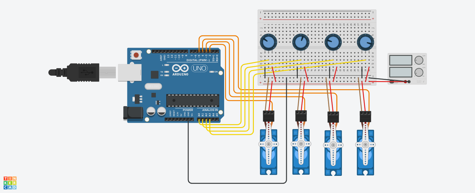
Circuit diagram: Arduino Uno wired to four potentiometers on a breadboard and four servos
The circuit. Four potentiometers on a breadboard feed analog pins A0–A3; each is mapped 0–1023 to 0–180Β° and written straight to its servo on pins 2–5.
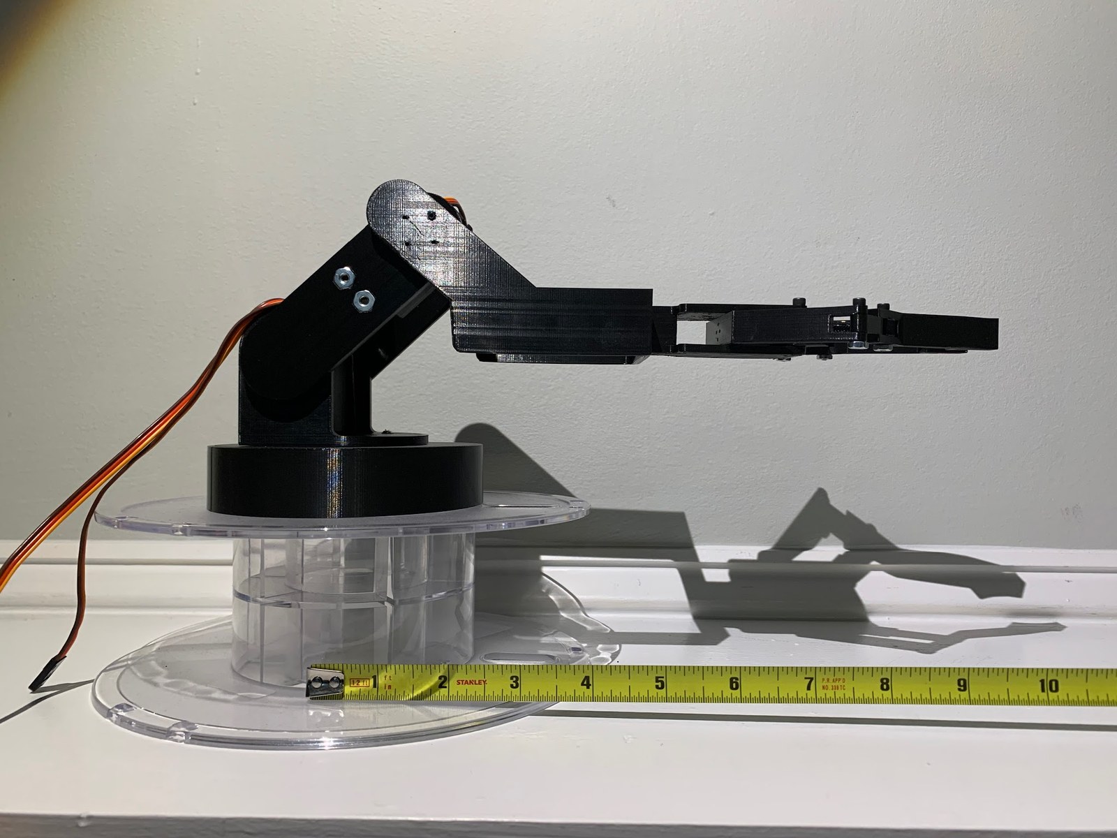
The finished 3D-printed arm on its spool base, measured against a tape
As built, mounted on a clear filament spool used as the base.
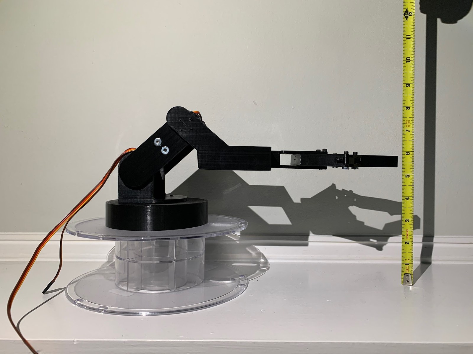
The arm photographed against a vertical tape measure showing its height
Height check against a vertical tape measure.
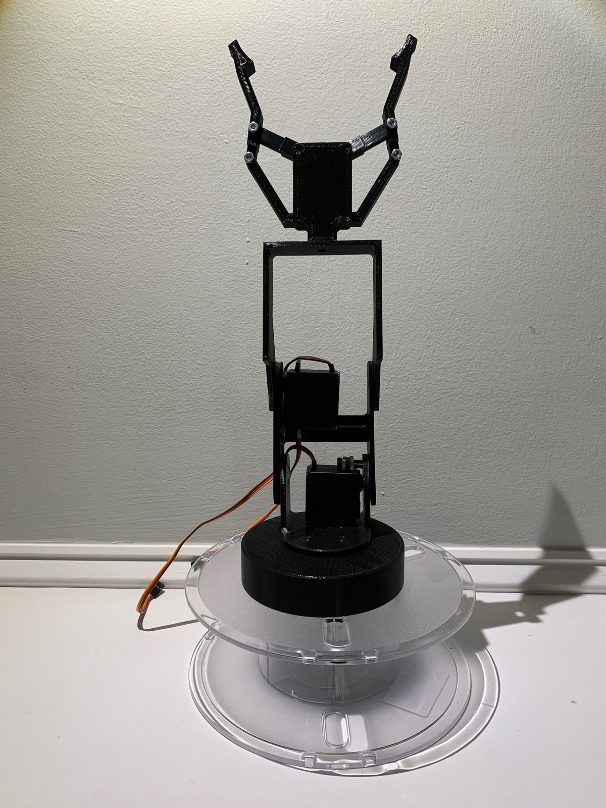
The assembled arm with the claw extended
Fully extended, claw open, with the servo leads run back down the arm.
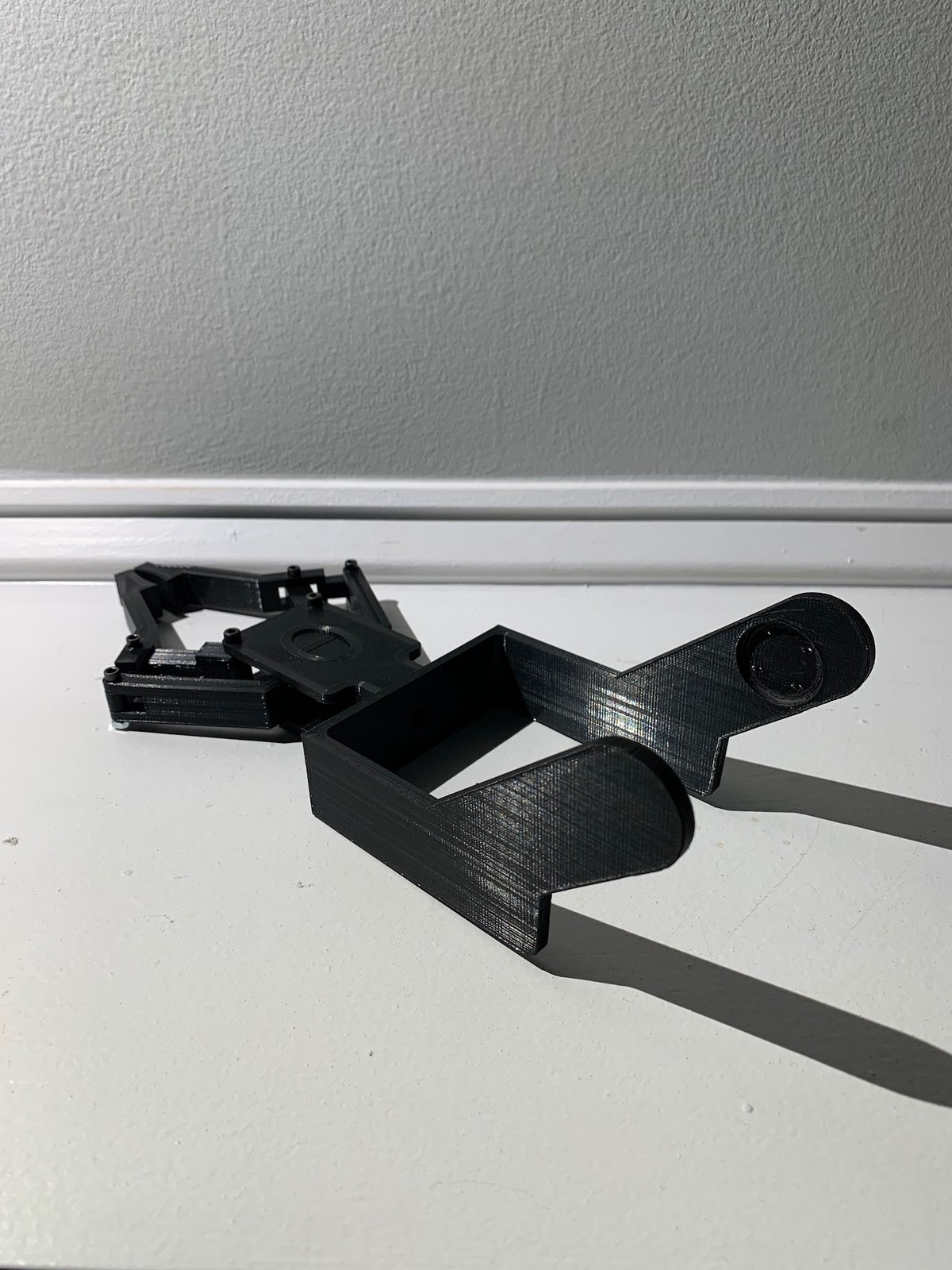
Close-up of the printed claw and four-bar linkage
The claw and its four-bar linkage, driven by a syringe pair off a servo horn.
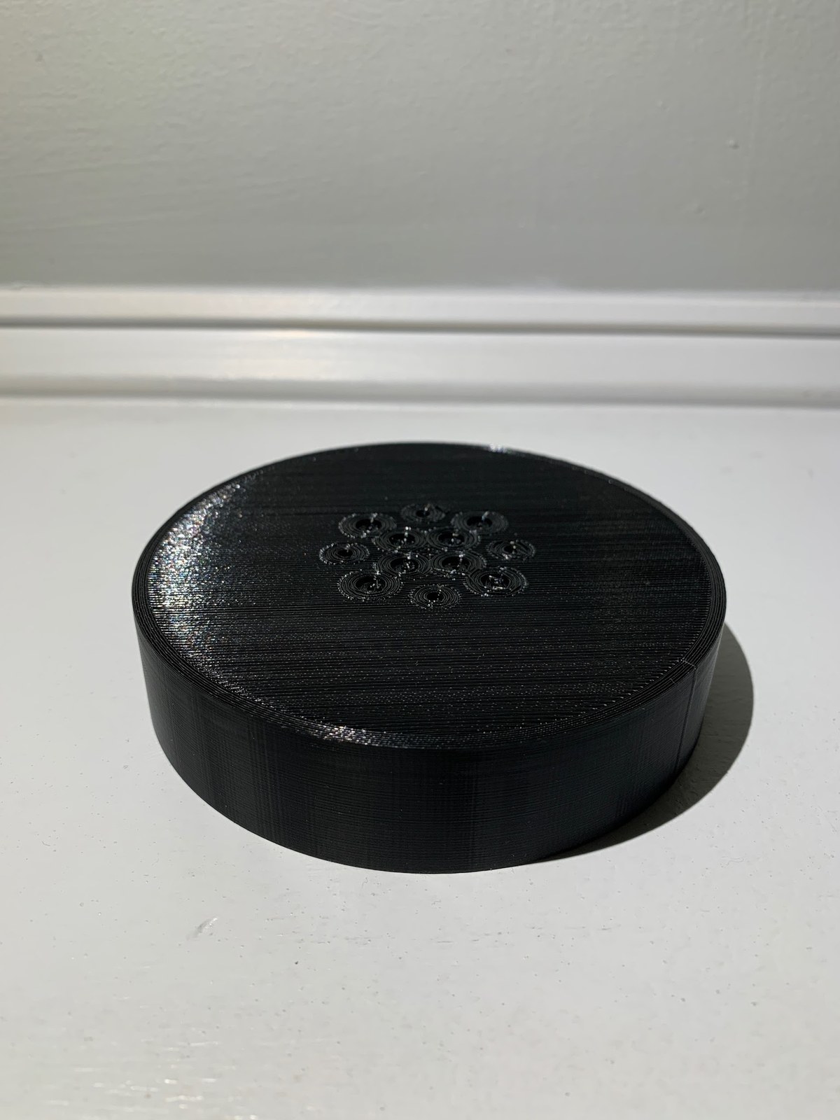
The printed base cap showing its bolt circle
Base cap, with its bolt circle sized to fit the spool base.

Dual-Axis Solar Tracker

Ten panels held normal to the sun on two axes, hunting the light with four photoresistors and an Arduino.

Role
Project manager
Team
G.A.S.E. Β· 4 engineers
Discipline
Electromechanical / controls
Outcome
Working two-axis prototype

Chasing the light

Solar panels convert roughly 22% of the light that reaches them, and they only do it while pointed at the sun. A fixed panel gives up a large share of its day to angle alone. The Germanna Association for Solar Energy set out to recover some of it.

Four photoresistors sit in a voltage-divider bridge at the corners of the array, feeding analog pins A0–A3. The loop reads all four each pass, compares them quadrant against quadrant, and steps the servo toward whichever corner is reading brightest β€” so the array walks itself into alignment rather than computing a sun position. We developed the control logic in MATLAB first, then ported it to the Arduino.

The requirements were three panels minimum, one axis minimum, sensors required, and a 12-inch cube envelope. We delivered ten panels on two axes inside it, feeding a USB breakout.

What I'd do differently

We were too ambitious too early. The right order would have been to meet the minimum requirements first and add capability on top of a working baseline β€” instead, CAD came late and the build kept drifting off the model, which made the workload hard to balance across four people. It's the lesson I've carried into every project since.

System specification
Axes of rotation
2
Solar panels
10
Photoresistors
4
Servos
2Γ— MG995
Torque
~1 NΒ·m
No-load current
170 mA
Stall current
1.2 A
Controller
Arduino Uno
Supply
4Γ— AA, ~6 V
Output
USB breakout
Envelope
12 Γ— 12 Γ— 12 in

Design to demonstration

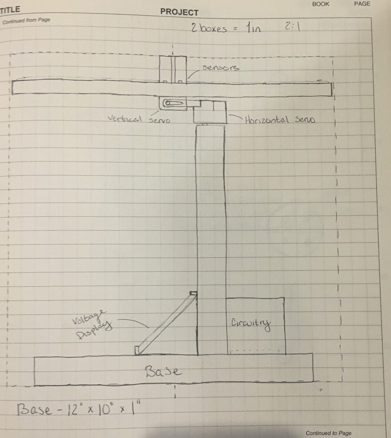
Madeline's hand-drawn side elevation of the tracker: sensors above the panel, vertical and horizontal servos below it, a support pole, and a voltage display and circuitry box on the base
My concept β€” side elevation. Sensors above the panel, vertical and horizontal servos beneath it, and a voltage display and circuitry box on a 12 Γ— 10 Γ— 1 in base. Drawn at 2:1.
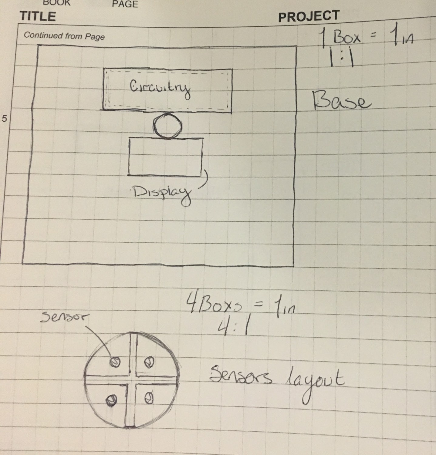
Madeline's hand-drawn top view of the base with the circuitry box and display either side of the pole, and a sensor layout of four sensors in quadrants
Base and sensor layout. Top view of the base with the circuitry box and display either side of the pole, and the four light sensors split into quadrants by a cross-shaped divider.
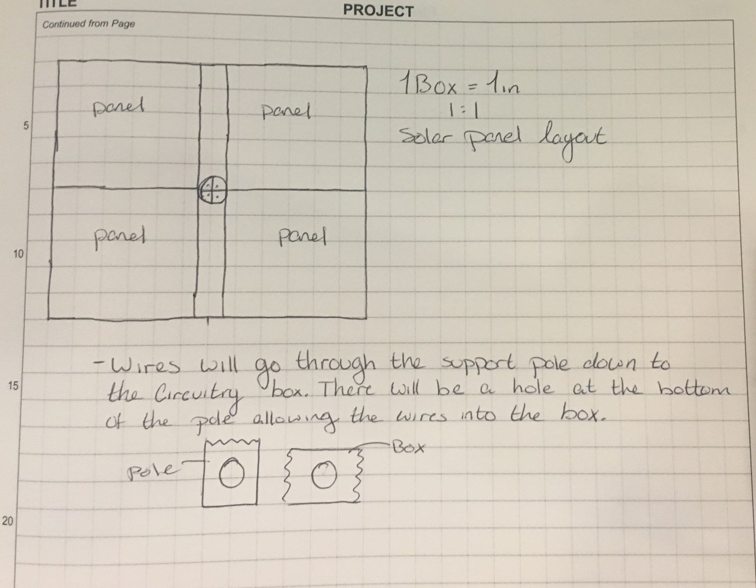
Madeline's hand-drawn solar panel layout: four panels around a central sensor mount, with a note that wires run through the support pole into the circuitry box
Panel layout and wiring. Four panels around a central sensor mount, with the wiring run down inside the support pole and into the circuitry box through a hole at its base.
The completed dual-axis solar tracker standing on a table
The prototype. Band-sawn base, PVC mast, laser-cut acrylic panel mount, 3D-printed motor mounts, and two metal electrical boxes.
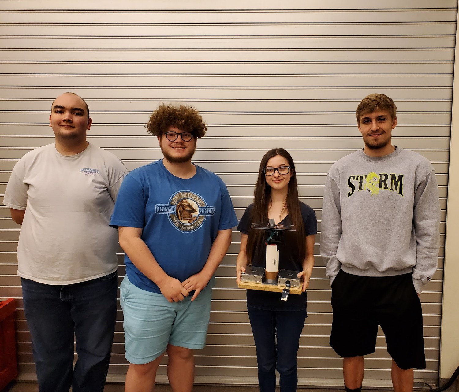
The four-person G.A.S.E. team with the finished tracker
The G.A.S.E. team with the finished prototype.

Madeline Crum

Aerospace Engineer

Virginia Tech aerospace engineering graduate focused on test and integration, space systems, and hands-on hardware β€” from a NASA RASC-AL finalist Mars mission to hydraulic robotics and closed-loop solar tracking.

Based in
Los Angeles, CA
Relocation
Willing to relocate
Madeline in her Virginia Tech graduation cap, gown, and stoles, sitting on a stone wall on campus

Design, Build & Test

Environmental Management Subteam Lead

Aug 2024 – Jun 2025

Project VESTA β€” NASA RASC-AL Finalist Β· Mars construction precursor mission

  • Led environmental management and systems-integration planning for a Mars precursor mission supporting sustained human surface operations.
  • Applied hazard-analysis findings to habitat-deployment logistics, surface infrastructure, construction operations, and overall mission architecture.
  • Developed an Analytic Hierarchy Process–based framework to prioritize crew and system risks from dust, radiation, thermal extremes, and other environmental hazards.
  • Integrated multidisciplinary subteam inputs into technical documentation, engineering figures, and the final NASA RASC-AL presentation.
Automated Solar-Tracking Panel

Design, Build, and Test

  • Designed and built an instrumented closed-loop tracking system using photoresistor sensors, mechanical rotation components, and control logic developed in MATLAB and ported to Arduino.
  • Identified a morning sunlight-reacquisition failure mode through repeated testing and iterated on the control strategy to correct it.

Hydraulically Actuated Robotic Arm and Gripper

Design, Build, and Test

  • Led design, fabrication, and testing of a hydraulic manipulator and gripper, verifying handling performance across objects ranging from small screws to approximately baseball-sized items.

Wind Tunnel Testing

  • Conducted supersonic wind-tunnel pressure testing and airfoil smoke-flow visualization across varied pitch and airflow conditions.

Experience

Independent Technical Development and Project Work

Jun 2025 – Present

Approx. 40 hrs/week

  • Startup Support β€” Provided project-based technical and operational support to R&D and operations at an early-stage startup.
  • Independent Engineering Development β€” Built SolidWorks skills by developing a multi-component V6 engine CAD assembly using part modeling, assembly mates, and design intent.
  • Technical Training β€” Completed introductory Altium Designer training in schematic capture, component selection, ECAD workflow, and PCB-layout fundamentals.

CAD Drafter

Mar 2021 – Sep 2021

Express Technologies Inc. Β· 40 hrs/week

  • Produced 2D AutoCAD drawings, schematics, and permit-ready documentation for fiber-optic infrastructure using satellite imagery.
  • Analyzed utility infrastructure, geographic constraints, state regulations, and specifications to determine feasible installation pathways.
  • Developed cable-routing designs used by engineering teams, contractors, and permitting authorities.
Email me